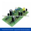
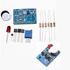
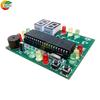
Quantity : 1
High-concerned chemical : none
Package : SOP
is_d : Yes
Supply Voltage : DC 5V
Type : Module
Brand Name : DIY NOW
Origin : Mainland China
Condition : New
Working Principle:
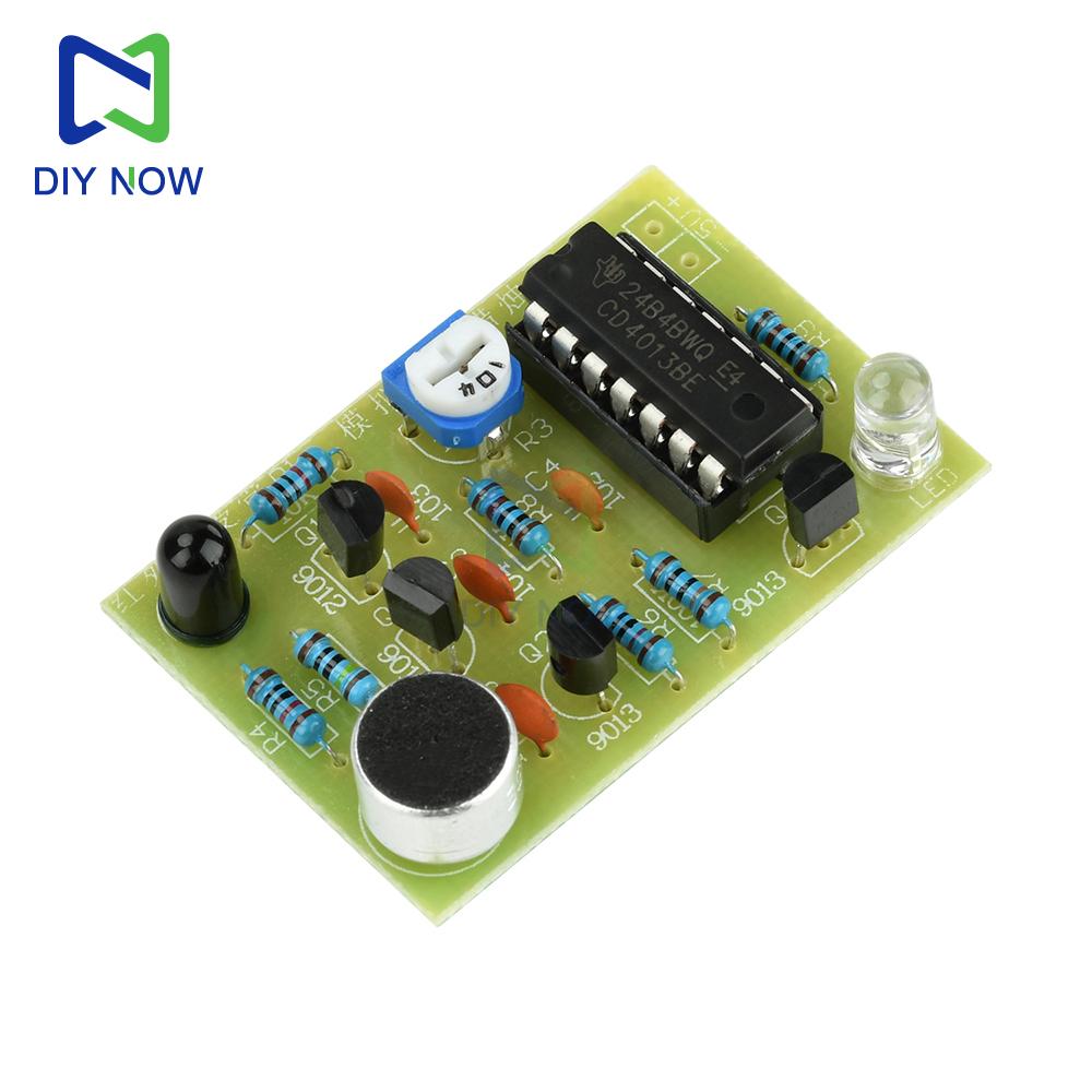
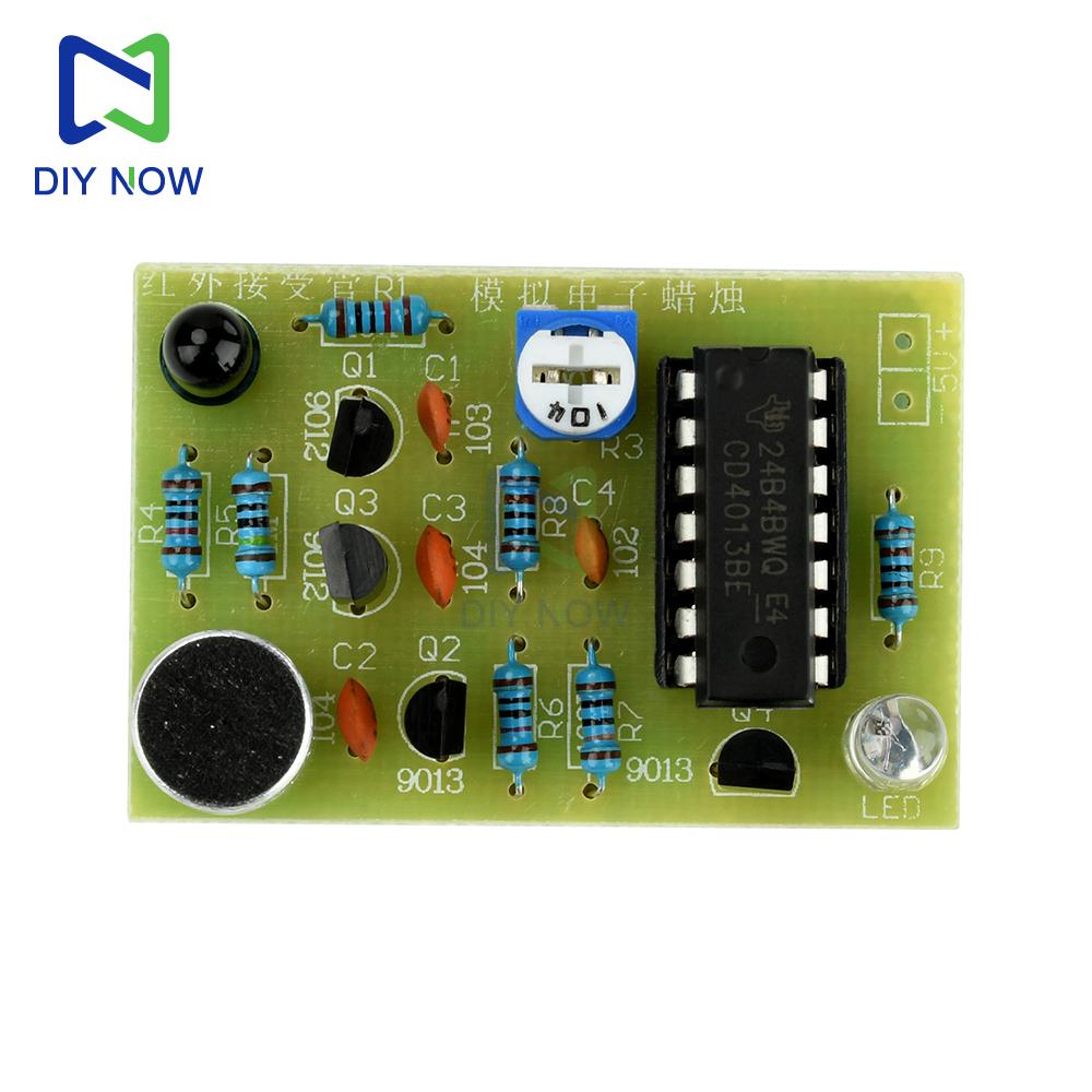
This electronic candle circuit utilizes one of the D flip flops CD4013, which is connected in the form of an RS flip-flop. After the power is turned on, the differential circuit composed of C3 and R7 generates a high-level differential pulse to the IRD terminal of U1, forcing the circuit to reset. Terminal 1 outputs a low level, which is sent to the base of transistor Q4. Q4 is turned off and the light-emitting diode does not light up.
When a lighter is used to approach the infrared receiving diode HW, the infrared diode is in reverse breakdown conduction, and the resistance suddenly decreases. The base of Q1 shows a low level state, and the transistor Q1 conducts. The high-level pulse generated by the collector is sent to the ISD terminal of U1,
Change the 1Q terminal from low level to high level, and send it to the base of Q4 through resistor R8. Q4 conducts and the light-emitting diode lights up. This process is equivalent to lighting a candle with a lighter. Even if the lighter leaves the infrared receiver tube, the circuit state will not change, and the light-emitting diode will remain lit. When blowing air into the electret microphone MIC with the mouth, the audio signal output by the microphone MIC is amplified by C2 and sent to Q2. The amplified electrical signal drives Q3 to conduct, and the output pulse signal is sent to the 1RD terminal of U1 to obtain a high-level differential pulse. The trigger is reset, 1Q becomes low-level, Q4 is cut off, and the LED is turned off, achieving the effect of wind blown candle extinguishing. The sensitivity of light intensity can be adjusted by potentiometer R3.
Parameter:
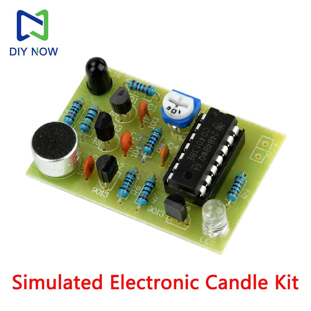
Kit Name: Analog Electronic Candle
Working power supply: DC 5V
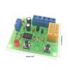
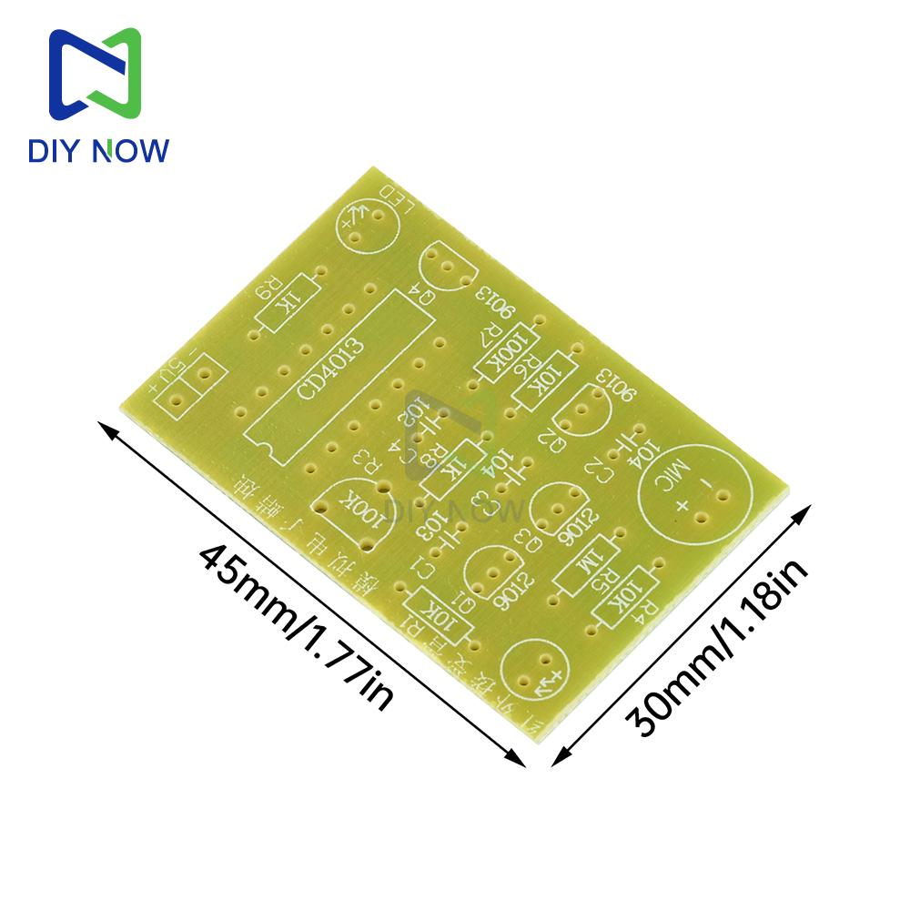
PCB board size: 45 * 30mm
Circuit board function: Simulate ignition, blow candles, full of fun, realize the function of electronic candles.
Function description: The simulated electronic candle has the simulation of "match ignition, wind blowing fire extinguishing", and the design prototype is derived from real-life scenarios. After the circuit modification, it can be used for birthday parties.
Welding instructions:
1. Pay attention to distinguishing the resistance value of each resistor and correspond one-to-one with the resistance value marked on the board.
2. Pay attention to distinguishing the capacitance value of each capacitor, and also correspond one-to-one with the resistance value marked on the board.
3. There are 9012 and 9013 transistors, please pay attention to the model before soldering.
4. Both the black infrared receiver tube and the transparent LED have long pins with positive terminals.
5. The chip notch direction and the base notch direction should be consistent with the notch direction marked on the board.
6. Insert the microphone head according to the shape on the board and cover the identification ring exactly, or the pin connected to the shell is negative.
7. The power supply should have a DC voltage of 5.0V, and pay attention to the positive and negative poles.
8. Pay attention to checking for welding short circuits and virtual welding before powering on.
9. The test should be conducted in a dark environment or with the infrared receiver tube in a dark environment. The test should be conducted in a bright place, which is equivalent to keeping the ignition on and the light on continuously.
Package Include:
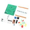
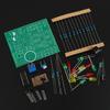
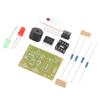
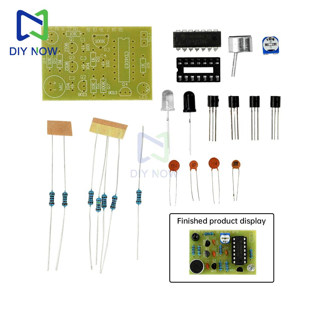
1X Electronic Candle DIY Parts
label:yes


 Teslim edilmediğinde para iadesi